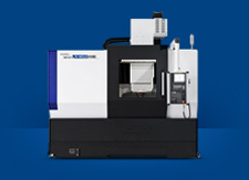
LF2600 II Series High Precision Spindle Front Loading CNC Turning Center
LF2600 II Series features high mobility through its compact size, making it suitable for tight spaces, and automated operations for maximizing productivity.
Front Loading Turning Center with Top Global Standard
- Increased rigidity by improving Z-axis structure
- Selection between roller LM guide and box guide way
- Stable unit composition with minimized thermal deformation
- Various types of gantry loader ensure effective & flexible automation
- A pleasant working environment by improving chip disposal ability
- Enhanced convenience by applying Fanuc’s latest controller
Basic Features
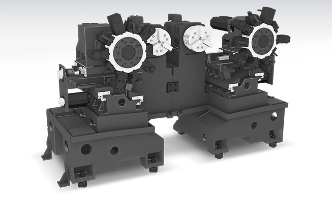
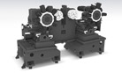
Optimized Layout and Design, Twin Spindle Front Loading CNC Turning Center
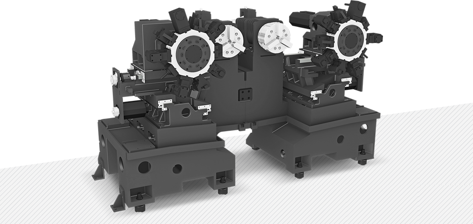
1Increased rigidity by changing the bed structure
In order to prevent decreased rigidity caused by load imbalance from sagging of the turret, and reduced lifetime of the give, LF2600 II Series increased the rigidity and realized high-precision product machining by designing protruded spindle headstock and Z-axis tool post.
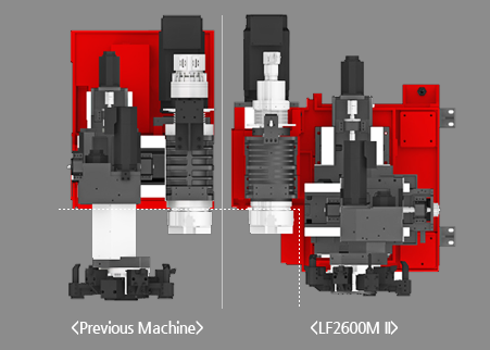
Reduced Protruded Length of Tool Post :
507 mm > 269 mm (238 mm shorter)
2High Precision Structure
Separated Bed Structure
The LF2600 II series is designed as a separated bed structure, minimizing thermal growth and vibration, ensuring stable cutting capability.
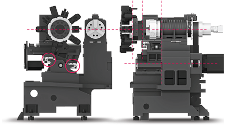
Z-axis Structure
Prevent sagging of the turret by reducing the protruded parts of the headstock by changing the structure of the Z-axis, and allow for high-precision machining of the product by increasing rigidity.
< Secure rigidity through shortest possible design of the outer guideway to the spindle >
Get Close to the Spindle of the Cascaded Z-axis and Expand Span > Increased Rigidity
3Roller LM Guide / Box Guide
The transfer axis of LF2600 II Series give options for roller LM guide and box guide to ensure optimum conditions according to machining characteristics. (Standard : Box Guideway)
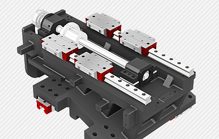
<Roller LM Guideway>
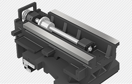
<Box Guideway>
Ball Screw
In order to eliminate thermal growth and to increase accuracy, all axes are driven by high precision double anchored ballscrews.

| Rapid Traverse Rate (X/Z) |
24/36 m/min |
| 24/24 m/min |
| Travel (X/Z) |
190/200 mm |
Spindle
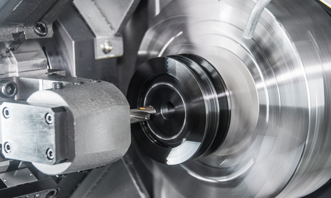
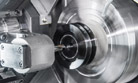
Heavy Duty Cutting & High Accuracy
1Spindle for Heavy Cutting
The spindle has the highest speed and torque in its class, which provides high performance during high speed/heavy duty cutting. Also the spindle is designed with [Ø110 (Ø4.3″)] size P4 angular contact ball bearings to minimize thermal displacement and increase accuracy.
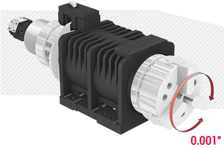
C-Axis Control (‘M’ Type)
C-axis of LF2600M II can be controlled to 0.001° which makes it possible to process various shapes.
Spindle Specifications
| Classification |
LF2600 II |
| Chuck Size |
Opt : 8″ or 10″ |
| Spindle Nose |
A2-6 |
| Distance Between the Sp. |
450 mm |
| Spindle Speed |
4,000 rpm |
| Motor (Max./Cont.) |
15/11 kW |
| Torque (Max./Cont.) |
254.5/140 N.m |
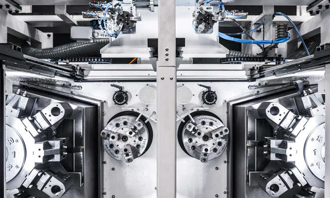
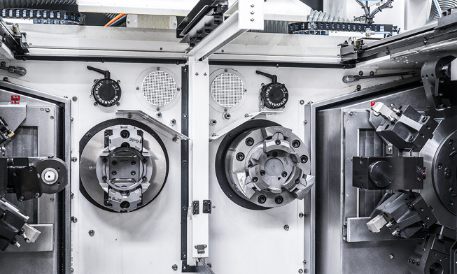
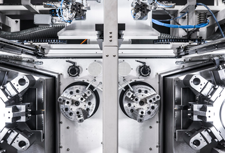
Greatly Increased Ability of Simultaneous Interrupted Machining of Right/Left Sides
R/L covers are separately designed to minimize the transfer of vibrations between equipment from interrupted machining or rough machining.
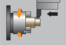
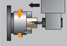
2Spindle Processing Flow
| 01 |
Parts requiring secondary operations are transferred from Z1 spindle to Z2 spindle |
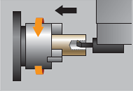
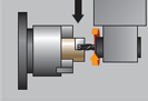
| 02 |
Same parts can be processed simultaneously by utilizing both spindles of Z1/Z2-axis with same parts. |
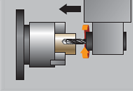
| 03 |
Different parts can be processed simultaneously by utilizing both spindles of Z1/Z2-axis with various parts. |
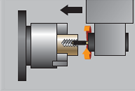
3Powerful Machining Capability
O.D Turning : Ø85(3.3″)
(Material : S45C)
| Machining depth |
4 mm (0.16″) |
| Spindle rpm |
796 rpm |
| Cutting speed |
210 m/min (8,268 ipm) |
| Forwarding speed |
0.5 mm/rev |
| Chip discharging amount |
420 cc/min |
Boring
(Material : S45C)
| Machining depth |
3 mm (0.12″) |
| Spindle rpm |
1,326 rpm |
| Cutting speed |
250 m/min (9,843 ipm) |
| Forwarding speed |
0.3 mm/rev |
| Max. boring depth |
4 times of boring bar dia. |
U-Drill
(Material : S45C)
| Tool Dia. |
Ø40 mm (Ø1 1/2″) |
| Spindle rpm |
828 rpm |
| Cutting Speed |
104 m/min (4,094 ipm) |
| Forwarding speed |
0.3 mm/rev |
| Chip discharging amount |
312 cc/min |
End Mill
(Material : S45C)
| Tool Dia. |
Ø16 mm (Ø5/8″) |
| Spindle rpm |
1,580 rpm |
| Cutting Speed |
76 m/min (2,992 ipm) |
| Forwarding speed |
0.165 mm/rev |
| Machining depth |
16 mm |
Dirill
(Material : S45C)
| Tool Dia. |
Ø16 mm (Ø5/8″) |
| Spindle rpm |
1,580 rpm |
| Forwarding speed |
0.35 mm/rev |
| Cutting speed |
80 m/min (3,150 ipm) |
Tapping
(Material : S45C)
| Tool Dia. |
M20 (M 3/4″) |
| Spindle rpm |
88 rpm |
| Forwarding speed |
2.5 mm/rev |
| Cutting speed |
5 m/min (197 ipm) |
※ The above result might be different by types of processing circumstances.
Automation System
Various Devices for User Convenience
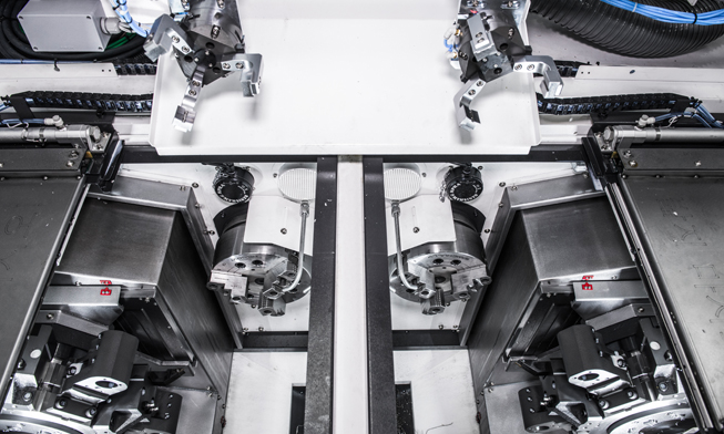
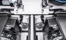
1Gantry Loader Machining Process
The high speed gantry loaders and the work stocker allow the implementation of automation cells. This enables machining process flexibility and productivity enhancement.
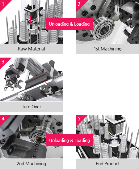
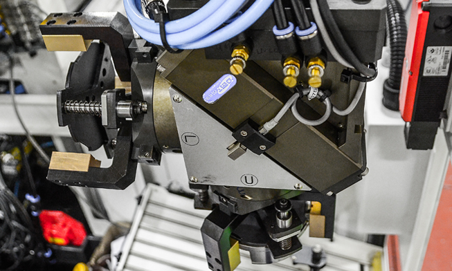
2Gantry Loader System
Gantry loader transfers raw material from in-stocker to machine automatically, starting machining process. Gantry automation provides good equipment access during operation and easy work monitoring, program modification and maintenance. In addition, small installation area facilitates optimized factory layout.
Gantry Specifications
R/L covers are separately designed to minimize the transfer of vibrations between equipment from interrupted machining or rough machining.
| Max. Work Weight |
3 kg (6.6 lb) |
6 kg (13.2 lb) |
| Max. Work Size |
Ø200×120L (Ø7.9″×4.7″L ) |
| Gantry Speed |
X-axis |
210 m/min |
150 m/min |
| Y-axis |
180 m/min |
130 m/min |
| Z-axis |
60 m/min |
| Loading Time |
5.7 sec |
7.8 sec |
※ The above loading time may vary depending on changes in the weight of the workpiece.
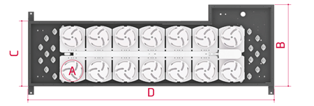
Stocker Specifications
| Work Size |
Ø180 (Ø7.1″) |
Ø200 (Ø7.9″) |
| Max. Work Height |
450 mm (17.7″) |
| Max. Work Weight |
35 kg (77.2 lb) / Pallet |
| No. of Pallet (EA) |
Ellipse Type : 10, 12, 14, 16 / Ring Type : 6 |
| Dimensions (A/B/C) |
Ø220/850/680 mm |
Ø240/930/760 mm |
| Pallet (D) |
10 EA |
2,130 mm (83.9″) |
| 12 EA |
2,330 mm (91.7″) |
| 14 EA |
2,530 mm (99.6″) |
| 16 EA |
2,790 mm (109.8″) |